Introduction
This document lists the required parts and steps for building Design 3.
Please note, these steps have not been tested from beginning to end, but were written while building the system. If you notice any inconsistencies or other problems, please send a note.
Parts List
The following parts are necessary to build the rack part of the system:
Gator G-PRO-6U-19 6U space, 19 inch deep, molded polyethylene rack case
Yamaha-Revolabs Executive HD 01-HDEXEC-NM 8 channel wireless microphone system receiver (other parts are listed below)
TOA M-633D digital mixer with automatic resonance control and automatic feedback suppression
dbx 215s 2 channel graphic equalizer
TOA DA-250FH 4 channel 70V digital power amplifier, 250 W per channel, with indepently powered channels
CyberPower OR700LCDRM1U UPS (uninterruptible power supply) with LCD, charges while off, with on-battery alarm silence function
Radio Design Labs STM-1 microphone preamplifier for emergency use
Dual port USB charger such as AUKEY PA-U38
Penn Elcom R1269/1UK/12 patch panel with 12 Neutrik D-series holes
2x Neutrik NC3FD-S-1-B panel XLR female input: Markertek
4x Neutrik NC3MD-S-1-B panel XLR male output: Markertek
4x Neutrik NL4MP-ST panel speakON male output: Markertek (additional required for the transformer boxes below)
4x Neutrik NLT4MX speakON male connectors: Markertek
1 ft power cord (NEMA 5-15P to NEMA 5-15R) such as Cables To Go 03137
2x 15 amp 3-way grounded outlet splitter, such as CyberPower GT300RC2 or Axis YLCT-10
2x 3 ft 1/4 TS/mono unshielded speaker cables: Monoprice
2x 3 ft 1/4 TRS/stereo shielded audio cables: Monoprice
3 ft RCA audio cable: Monoprice
14x regular (5.08 mm pitch) Phoenix/Euroblock connectors, Phoenix Contact part #1757022 (for TOA M-633D mixer and TOA DA-250FH amplifier): Digi-Key 277-1012-ND
6x mini (3.81 mm pitch) Phoenix/Euroblock connectors, Phoenix Contact part #1803581 (for Yamaha-Revolabs receiver): Digi-Key 277-1162-ND
24x rack screws with washers (for mounting equipment in the rack)
4x power cords for the rack equipment
short extension cord, at least 2 ft, ground not required
For the custom 70V transformer boxes:
2x Polycase DC-34PMBYR enclosures
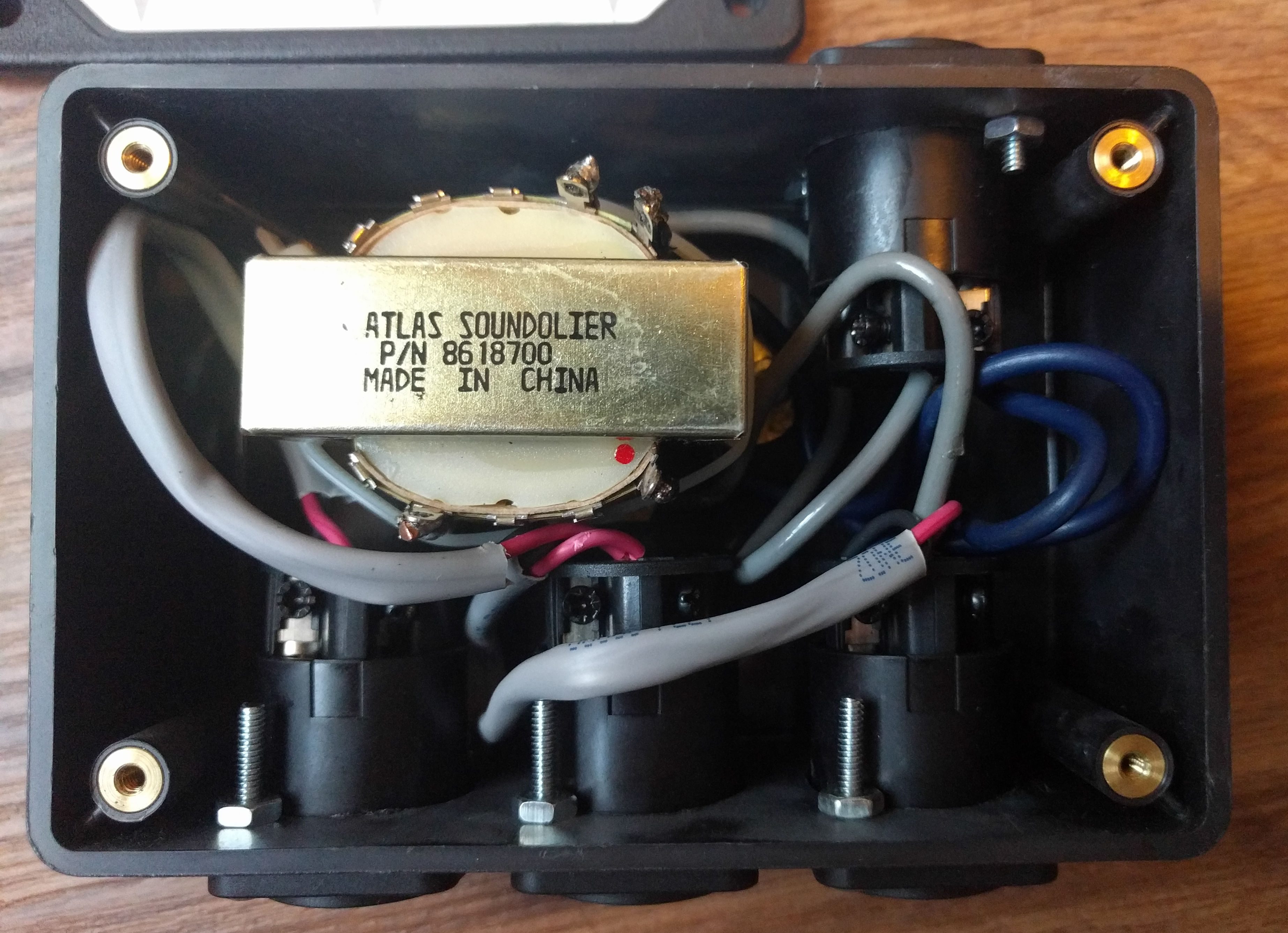
2x Atlas Sound T-20 70V 30W transformers
8x Neutrik NL4MP-ST panel speakON male outputs
50x Machine screws, Phillips flat head, Zinc plated steel, #4-40 x 1 inch: Bolt Depot
50x Hex machine screw nuts, Zinc plated steel, #4-40: Bolt Depot Markertek
You will also need this bulk cable (for both the rack part of the system and the 70V transformer boxes):
30 ft (order 40 ft) Belden 9451 22 AWG microphone/line cable: Markertek (or consider using heavier cable)
15 ft (order 20 ft) West Penn 25225B 16 AWG 2 conductor speaker cable: Markertek
These accessories are also necessary (must be stored and transported in a separate container):
4-6x Yamaha-Revolabs 01-HDXLRMIC-11 (wireless XLR adapters)
Yamaha-Revolabs 02-08HDCHG-C (charger base) with power supply (Yamaha-Revolabs 02-HDPWR-11 or other 24VDC 2A supply with barrel plug size 2.1mm I.D. x 5.5mm O.D. x 9.5mm)
4-6x Sennheiser e835 (dynamic wired microphones)
audio-technica AT8202 (adjustable in-line XLR attenuator): Markertek
Williams Sound PPA 250 T4 (assistive listening transmitter)
2x-10x Williams Sound PPA 250 R7 and batteries (assistive listening receivers)
2x-10x headphones for the assistive listening receivers
2x-10x stereo/mono adapters for the assistive listening receivers, such as the Radio Shack #274-368
MZQ 800 microphone clip (normally included with Sennheiser e835 microphone)
On-Stage Stands MY200 universal microphone clip
Atlas Sound GN-13E 13 inch flexible microphone gooseneck
Atlas Sound GN-19E 19 inch flexible microphone gooseneck
kV Connection KM-IPHONE-MICX-A22 XLR to TRRS adapter
4x 50 ft XLR cables, 20 AWG or larger: Technical Pro CXXF1650
4x 50 ft speakON cables, 16 AWG or larger: Technical Pro CSS1650
3 ft XLR cable, 20 AWG or larger: Monoprice 4750
2x 6 ft speakON cables, 16 AWG or larger: Monoprice 8768
2x 1.5 ft XLR female to 1/4 TRS/stereo male cables: Monoprice 4767
Hosa YXM-101.5 XLR Y/splitter cable
2x Neutrik NL4MMX (speakON gender changer for long cable runs): Markertek
25 ft power extension cord
Also consider the following (not tested):
2x TOA SR-H2L (line array speakers)
2x TOA MT-S0301 (matching 70V 30W transformers)
2x TOA SR-SA3 (stand adapters)
2x TOA ST-33B (speaker stands)
Building the Main System
Install the CyberPower power supply in the bottom space of the rack. Connect four power cables (for the other devices) to the first four (black) outlets on the rear.
Open the DA-250FH amplifier and set the input sensitivity and high-pass filter jumpers. Input sensitivity should be set to -10 and the high pass filter should be set to ON. See page 13 of the manual. The three rear switches (near the inputs) should be OFF (out).
Install the DA-250FH amplifier above the power supply, and connect the power cable.
Install the dbx equalizer above the amplifier, and connect the power cable.
On the rear of the M-633D mixer, set the AUTO MUTE switch to OFF and set all six input selector switches to LINE.
Install the M-633D mixer above the equalizer, and connect the power cable.
On the rear of the Yamaha-Revolabs receiver, switch all configuration DIP switches to the OFF (upward) position.
Important: update the firmware on the Yamaha-Revolabs base unit and all microphones using the HD Control Panel software.
Install the Yamaha-Revolabs receiver at the top space of the case and connect the power cable.
Install 10 Neutrik D-size panel receptacles in the patch panel:
XLR female (marked with F and has a PUSH release tab)
XLR male (marked with M)
speakON (twist connector)
XLR male
speakON
XLR male
speakON
XLR male
XLR male
speakON
(empty)
(empty)
Cut cable to 60 cm (2 ft) lengths. You need:
14 pieces of Belden 9451 and
6 pieces of Wes Penn 25225B.
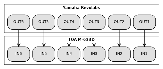
Connect the first 6 Yamaha-Revolabs outputs to the corresponding M-633D mixer inputs.
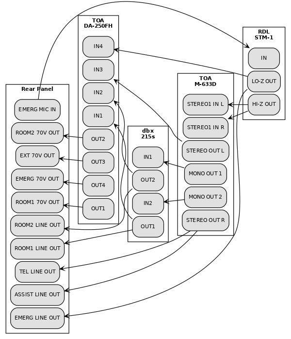
Use cables to connect equipment according to the following signal diagram. Note, XLR connections are 1=earth/ground, 2=hot, and 3=cold.
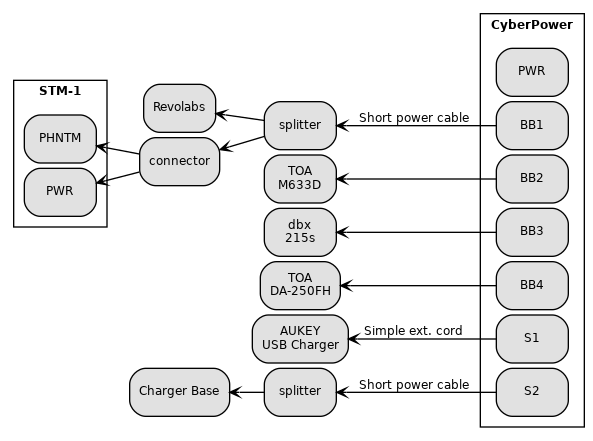
Use power cables to connect equipment according to the following diagram. The CyberPower BB outlets are battery-backed in case of a power outage, and are also controlled by the front switch. The S outlets are not battery-backed and are always on. It is important to connect these correctly so the charger base is powered while the system is off.
Install the rear patch panel to the rear rack.
Place labels. See Labels (PDF) (Inkscape SVG source).
Building the Custom Transformer/Splitter Boxes
Follow these instructions once for each of the two transformer boxes.
Screw the top cover onto the Polycase enclosure, if it is not already.
Use this template (PDF) (LibreCAD DXF source) to drill six small holes and three large holes on the front side of the Polycase enclosure. It may help to print extra templates, and to tape the template onto the enclosure while drilling.
Use the same template to drill two small holes and one large hole on the rear side of the enclosure.
Remove the top cover and drill two small holes in the bottom of the box for mounting the Atlas Sound T-20 transformer. Be sure to leave room for the speakON connectors; insert a speakON connector in each of the four holes to be sure.
Make the following connections. The transformer connections must be soldered. It may be helpful to use a plastic tie strap around the transformer to stabilize the wires during soldering, as well as for handling in the next step. For more information about the Atlas T20 transformer, see the datasheet (PDF).
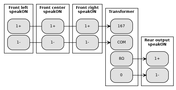

Inside the 70V transformer/splitter box
Use the #4-40 x 1 inch screws/nuts to mount the transformer and speakON panel connectors. It might be easier to start with the front left connector and work around counter-clockwise before mounting the transformer last.
Screw the top cover onto the enclosure again.
Place the label on the top cover. See Labels (PDF) (Inkscape SVG source).
Changes
2023-04-12: Updated rear switch settings for the M-633D mixer.
 Email
Email LinkedIn
 Twitter
 Reddit
 Facebook