Introduction
This design has two goals which are often difficult to accomplish in combination: portability and flexibility. The system is designed to be portable while also being useful in a broad variety of scenarios, particularly regarding outputs. For example, the system has already been successfully used in the following ways:
Multiple venues with less than an hour combined of setup and tear-down time
Two standard 8-ohm speakers, each in a separately controlled zone
Four 70V speakers, with two speakers per zone
Connected to a separate in-room system via a microphone level output with full control of microphone inputs, feedback suppression, room correction, etc.
Power outage with no effect on functionality and with the on-battery alarm silenced (tested in a live event with the same UPS and two 8-ohm speakers in Design 1)
The above scenarios do not require any additional equipment or accessories beyond what is pictured below and listed in the Building Guide. No system knowledge is necessary other than the willingness to carefully follow the instructions in the User Guide (though connecting to a separate system may require additional knowledge).
This design could also be used for permanent installation at a location. However, some steps and accessories could be skipped while building the system and during use, because no portability is required.
Features
This design provides the following features:
- Portable
The main system is in a 6U rack case (about 22×22×14 inches) and weighs about 80 pounds. The case has a handle on each side and can be carried fairly easily by two people. The case can be fully enclosed, for transport and storage, with front and rear doors. Required accessories, such as cables and microphones, fit in a small rolling suitcase.
- Two versatile room output channels
Each room output can be 70V, 8-ohm, line level, or microphone level; connectors can be speakON, 1/4 inch, XLR, or bare wire. This allows the system to be connected to and used with most pre-existing setups. A permanently installed in-house system only needs to have a microphone input, for example, and this system provides the accessories and instructions to correctly accommodate the signal levels. All necessary cables and adapters are included.
- Supports up to 6 wireless inputs
Inputs are provided by a Revolabs wireless microphone system. Most standard dynamic microphones will work with the Revolabs wireless XLR adapter.
- Automatic digital room correction
The mixer features TOA’s Acoustic Resonance Control (ARC), which will automatically measure the room response and generate a room correction curve. This can be used for up to two speaker zones.
- Automatic feedback suppression
The TOA mixer provides automatic feedback suppression on each input.
- Integration with conference calling
A XLR to TRRS cell phone interface allows any cell phone (with compatible audio input) to be used to share audio on a conference call.
- Emergency signal path
A fully isolated emergency signal path uses a separate microphone-level input, a separate amplifier channel, and separate line level and 70V outputs. (The TOA DA-250FH has power-isolated amplifiers. If the UPS fails, the amplifier can be powered directly.)
- Uninterruptible (battery backup) power supply
The UPS will provide power to the system in case of a power outage. The on-battery alarm (beeper) can be silenced (though the low-battery alarm cannot be silenced). The UPS will charge even when the system is powered off. Note that the UPS is not intended to power an in-room installed system that is being used via a line or microphone level link—in that case, it might be necessary to switch to a backup speaker.
- Assistive listening output
An output, a transmitter, receivers, and headphones are provided for people with difficulty hearing.
Current status
As of 2019-10-08, this system has been used in at least five different venues with total live time of at least 50 hours.
The Revolabs wireless microphone system has been used significantly less (I was testing the Sennheiser SpeechLine digital microphone system, but it performed very poorly).
While the CyberPower rackmount UPS works well for this purpose, I am not sure about the longevity of the device and its batteries. The UPS should be kept powered even when the system is in storage to reduce sulfation of the batteries. The system should also be occasionally tested on battery power to ensure adequate run-time.
Major components
Gator G-PRO-6U-19 (6U portable rack case)
Revolabs Executive HD 01-HDEXEC-NM (wireless microphone system)
Revolabs 01-HDXLRMIC-11 (wireless XLR adapters)
Sennheiser e835 (microphones)
TOA M-633D (mixer with automatic room correction and feedback suppression)
dbx 215s (2 channel graphic equalizer)
TOA DA-250FH (4 channel 70V amplifier)
CyberPower OR700LCDRM1U (uninterruptible power supply)
audio-technica AT8202 (adjustable in-line XLR attenuator)
Pictures
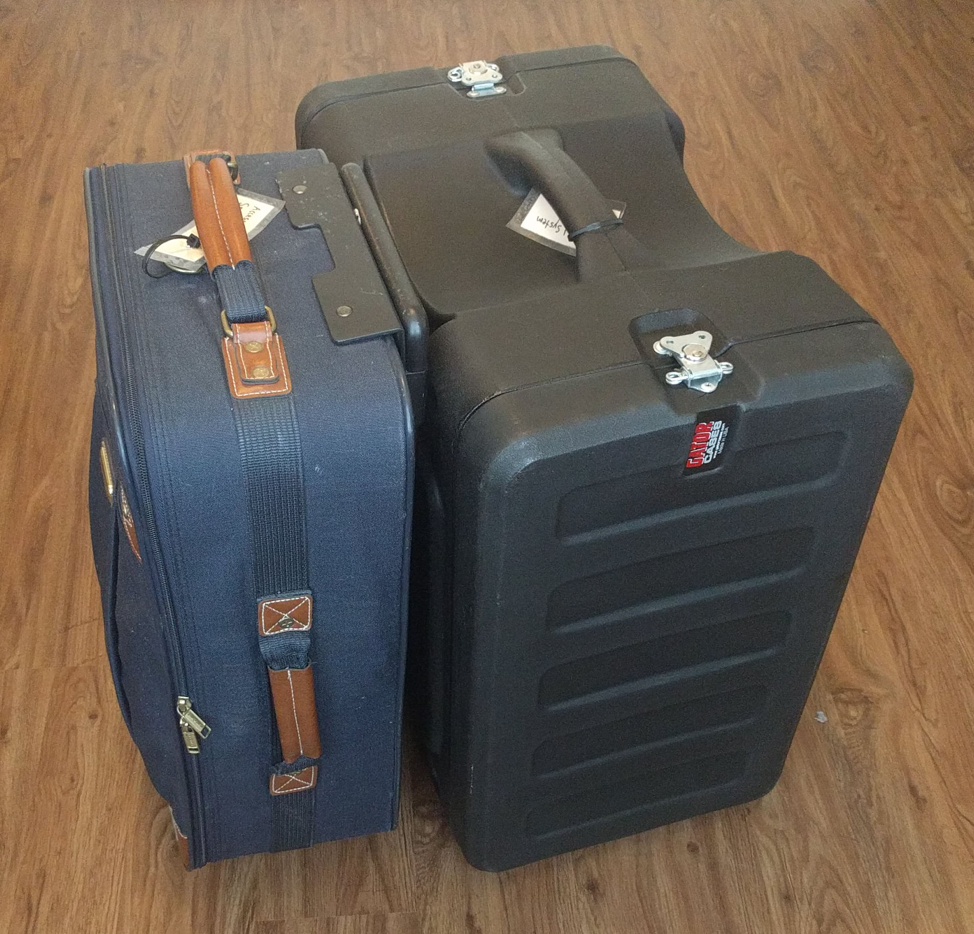
Packed
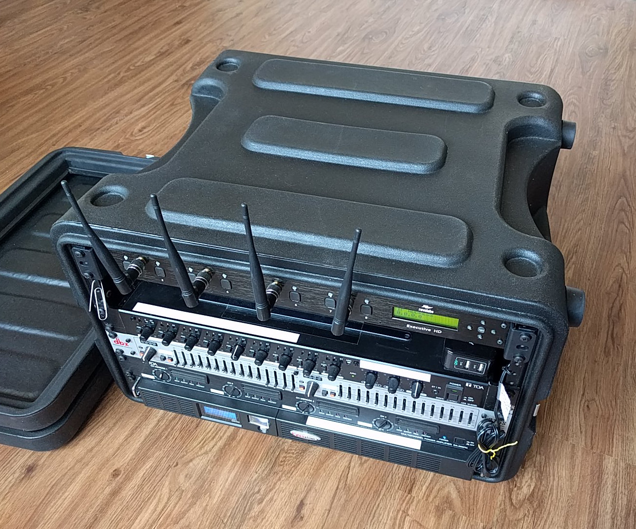
View from front, with no connections
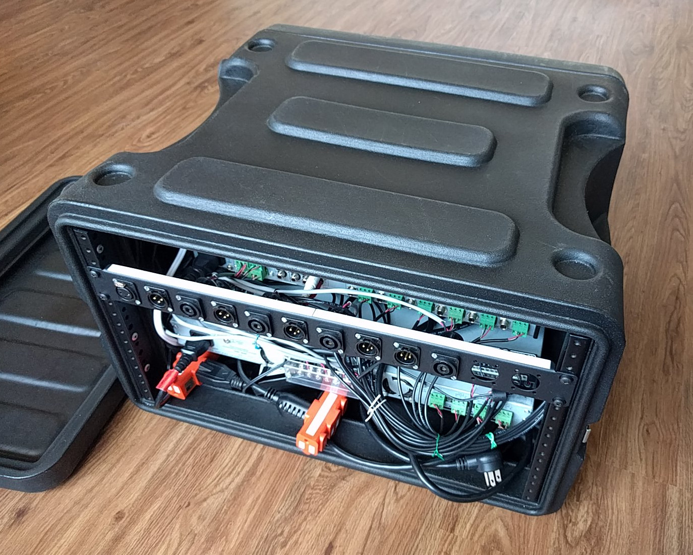
View from rear, with no connections
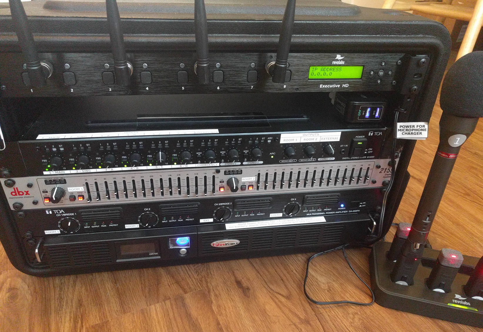
View from front, with microphone base connected
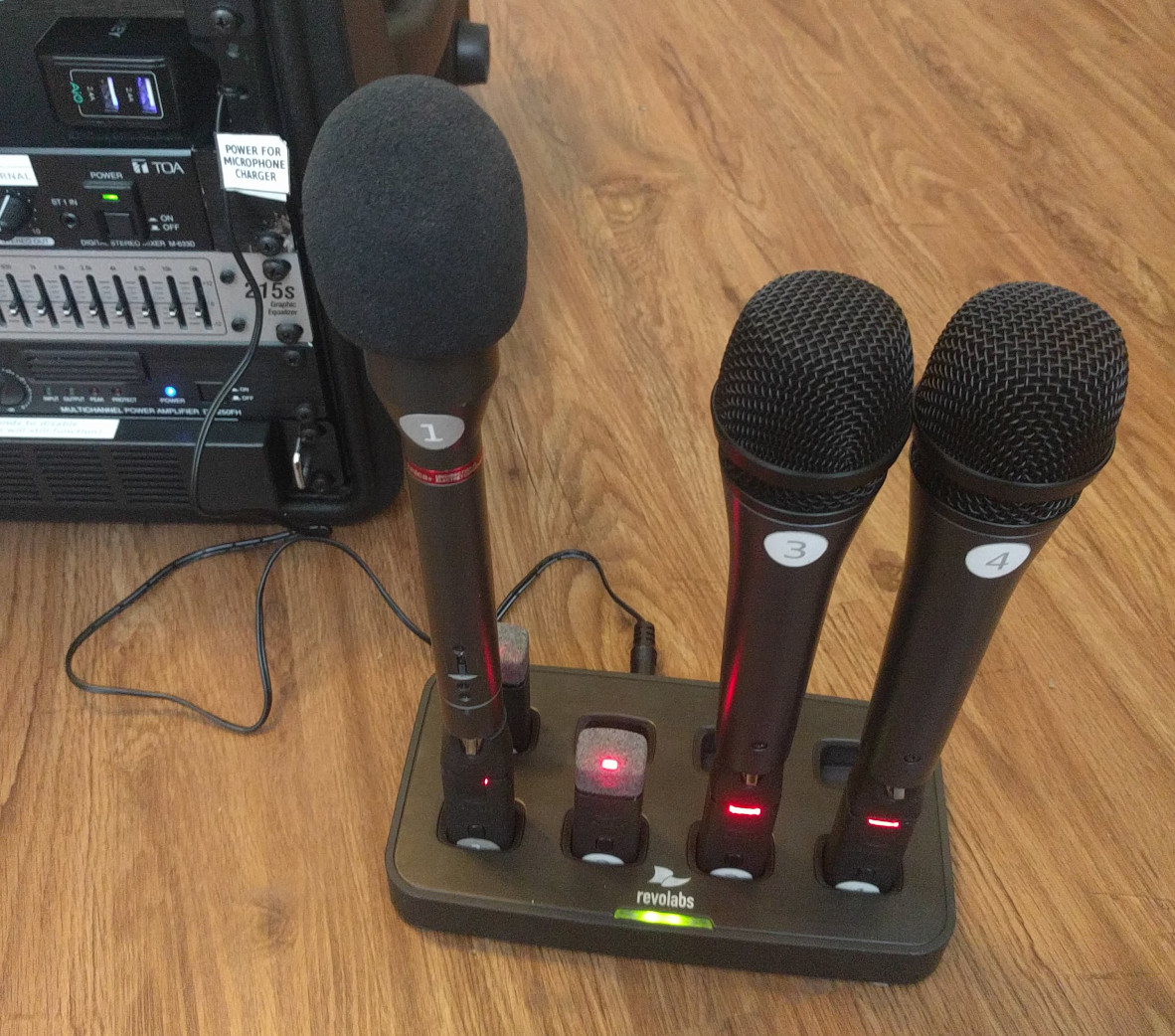
Microphones in charger base
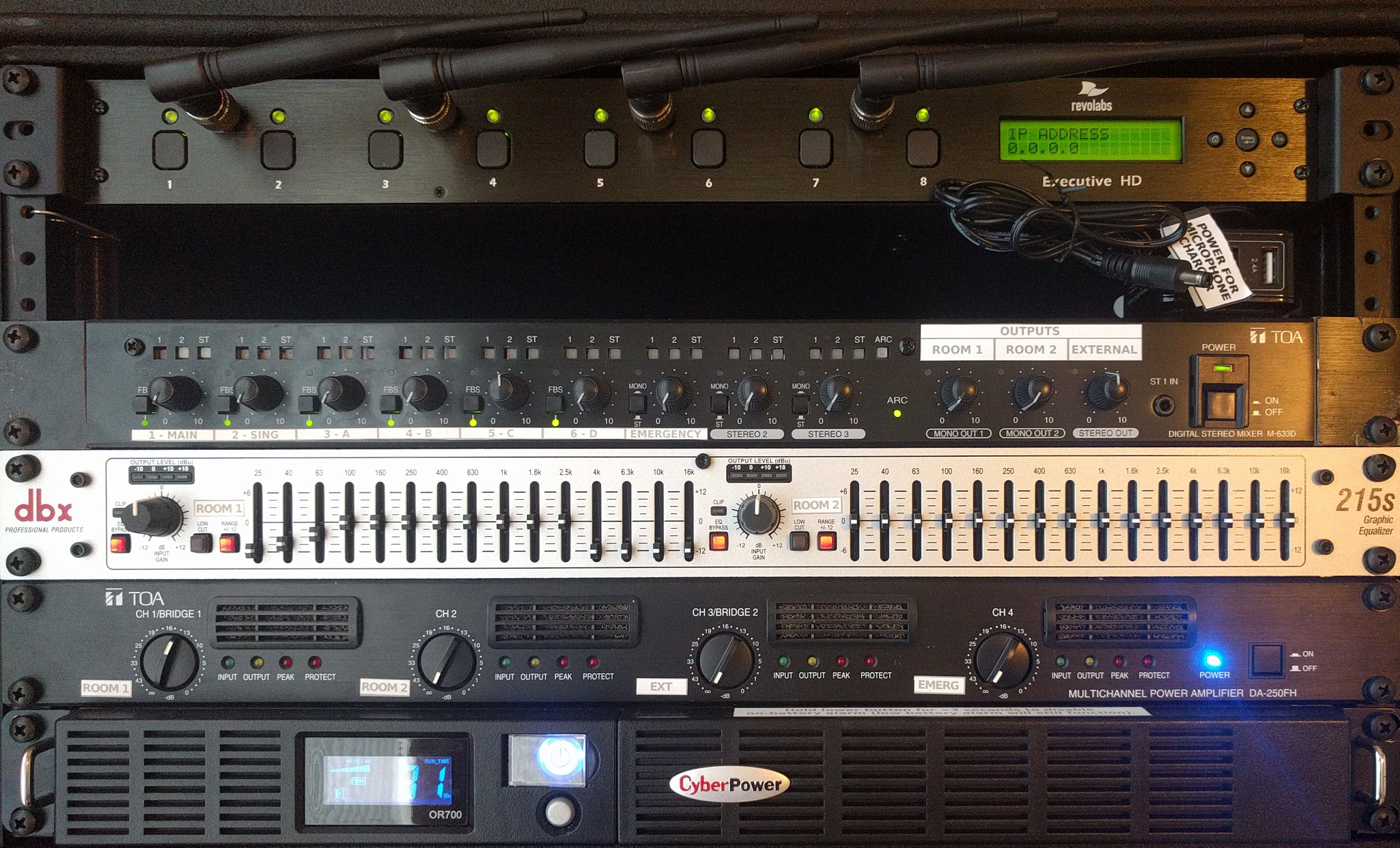
Front view of rack
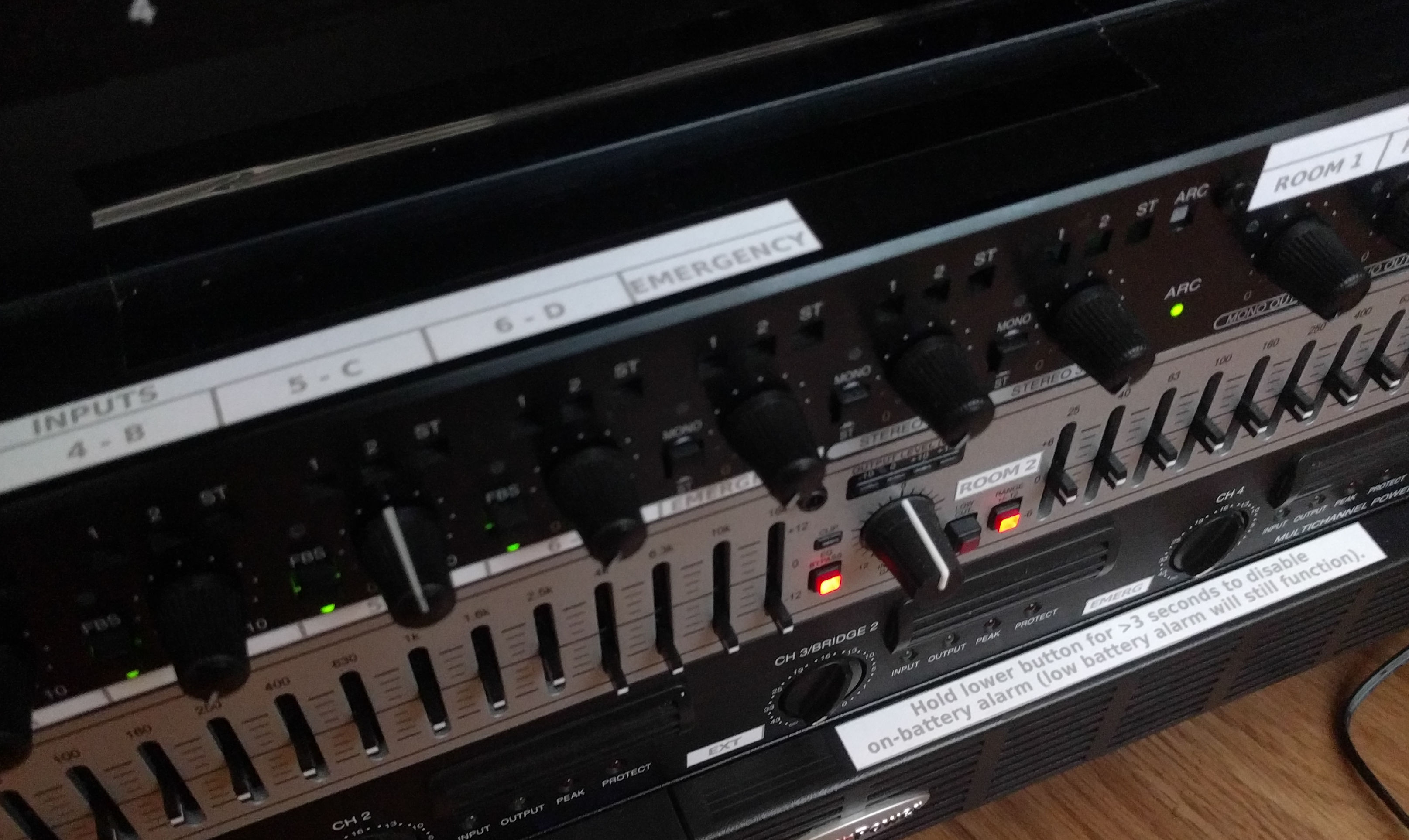
Labels on front
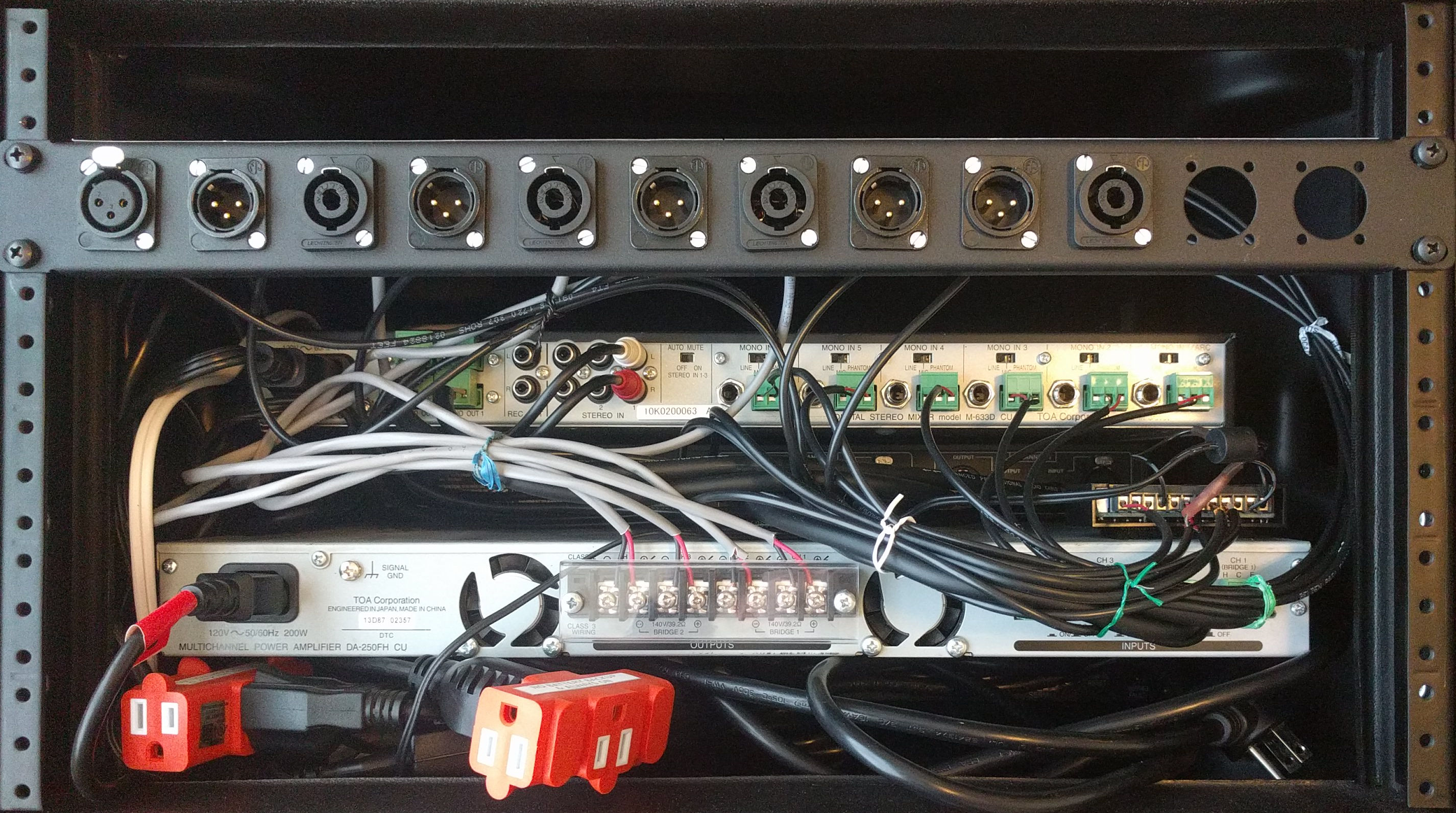
Rear view of rack
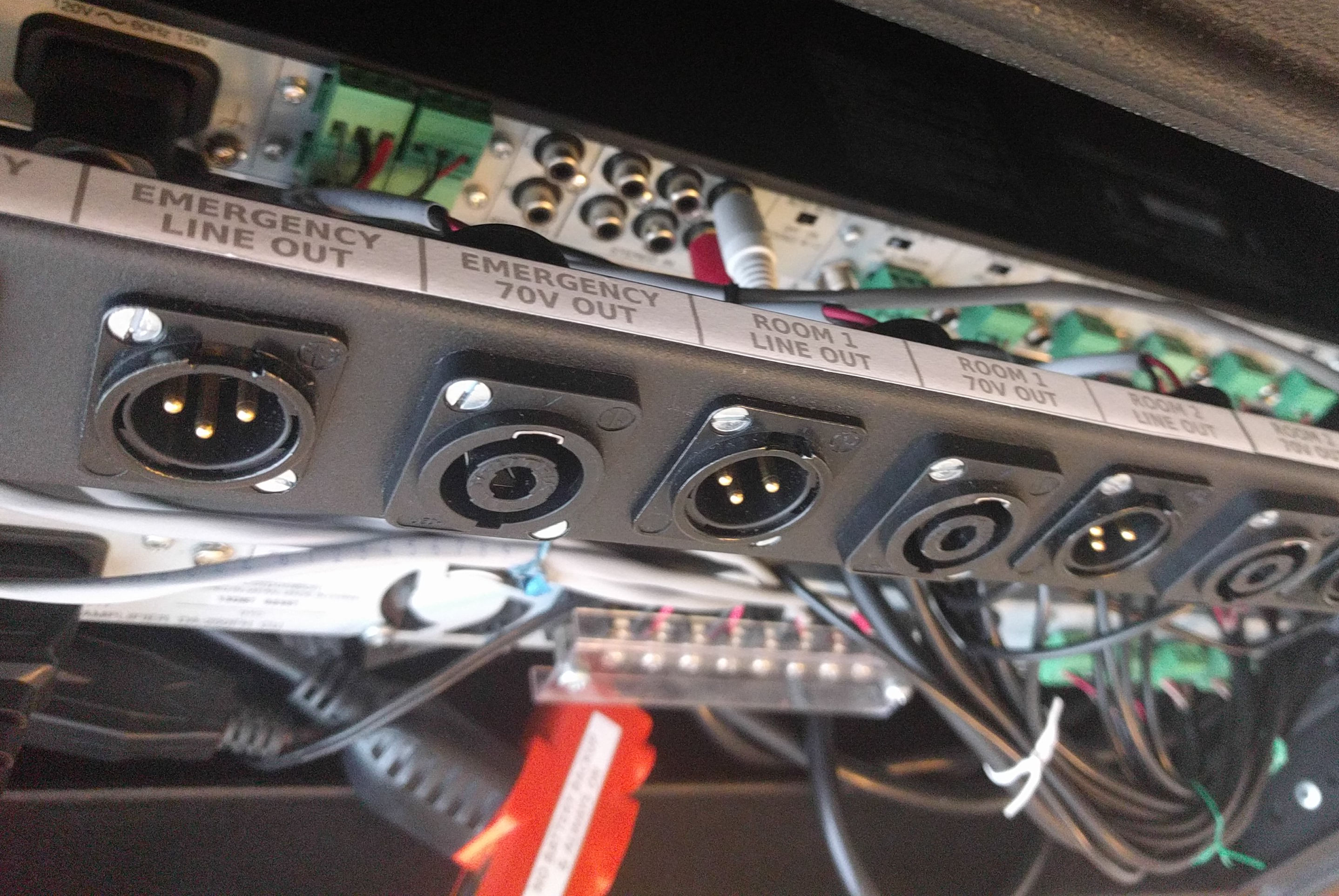
Labels on rear patch panel
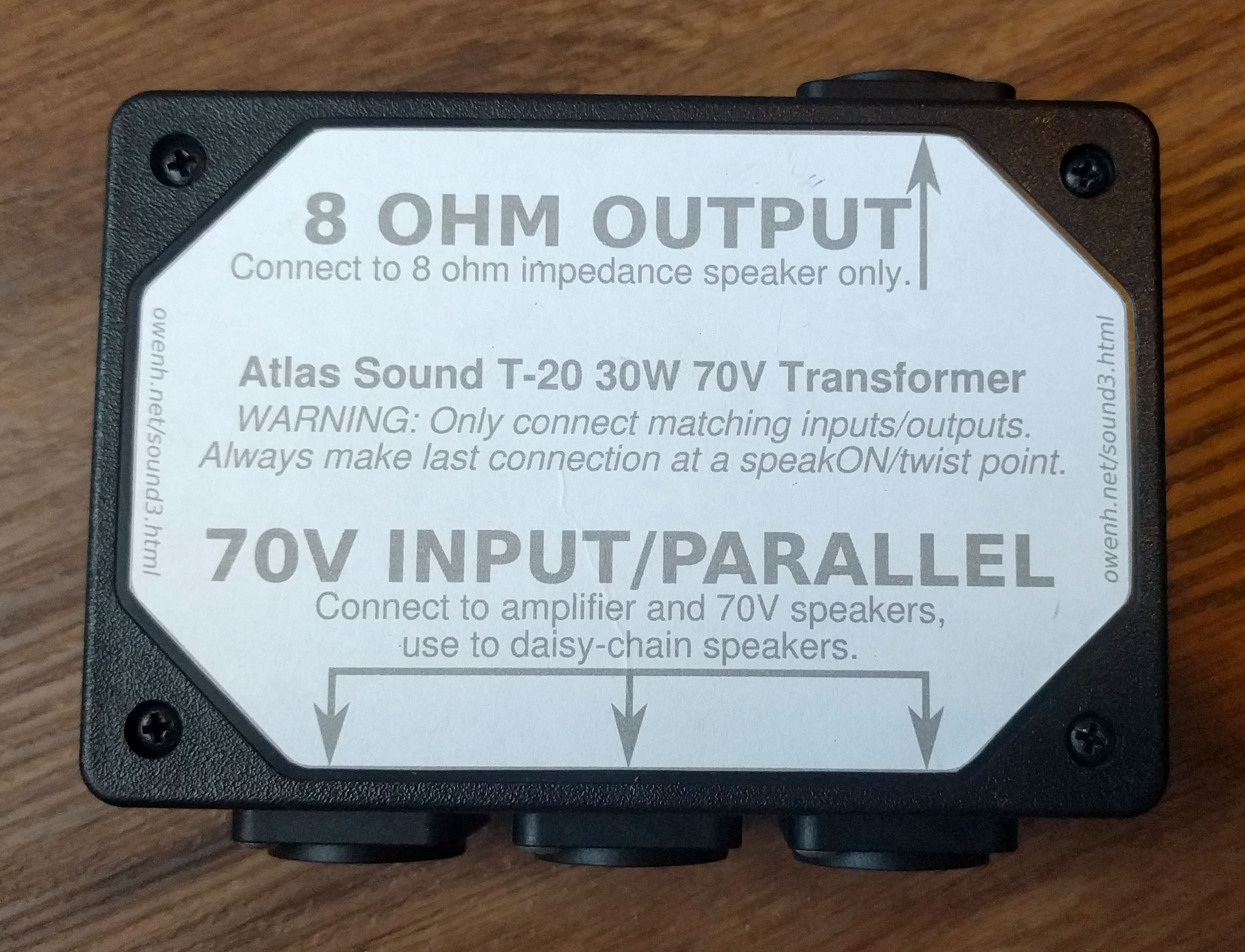
70V transformer/splitter box
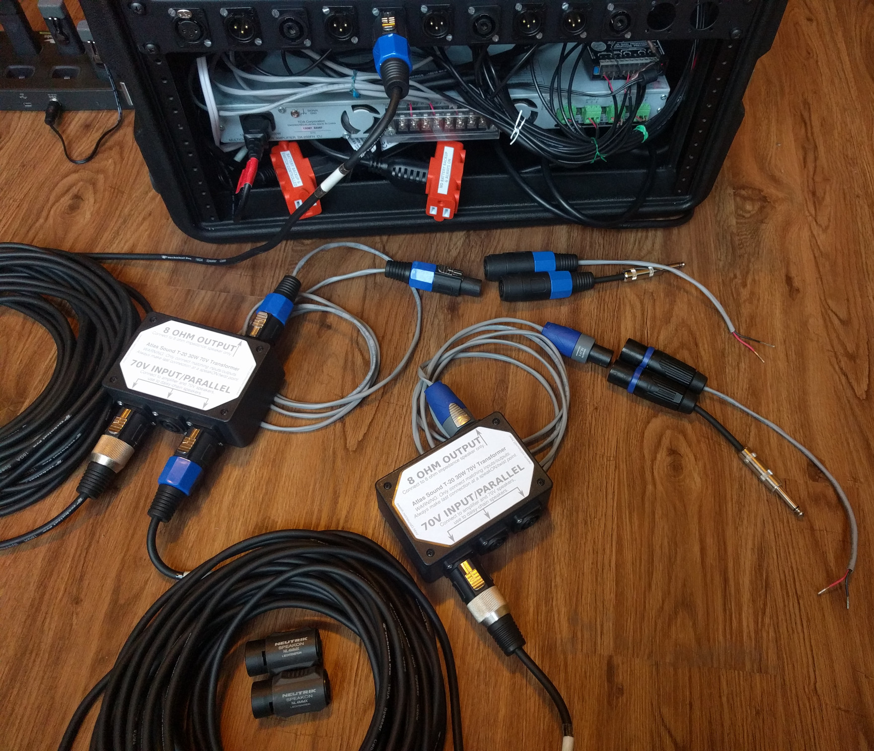
Output to two 8-ohm speakers on one channel, daisy-chained, with speakON, TS, or bare wire connections
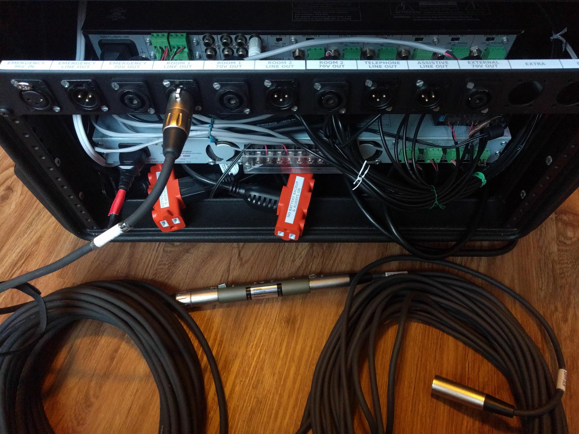
Output to secondary system, with microphone/XLR connection (omit attenuator for line level)
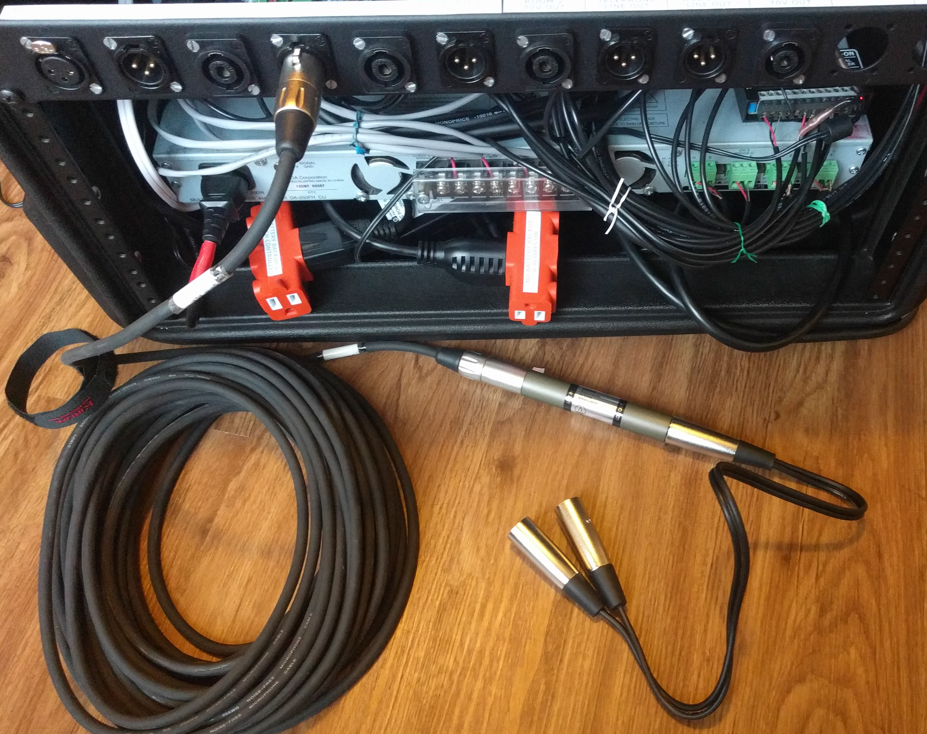
Output to two powered speakers on one channel, daisy-chained, with microphone/XLR connections (omit attenuator for line level)
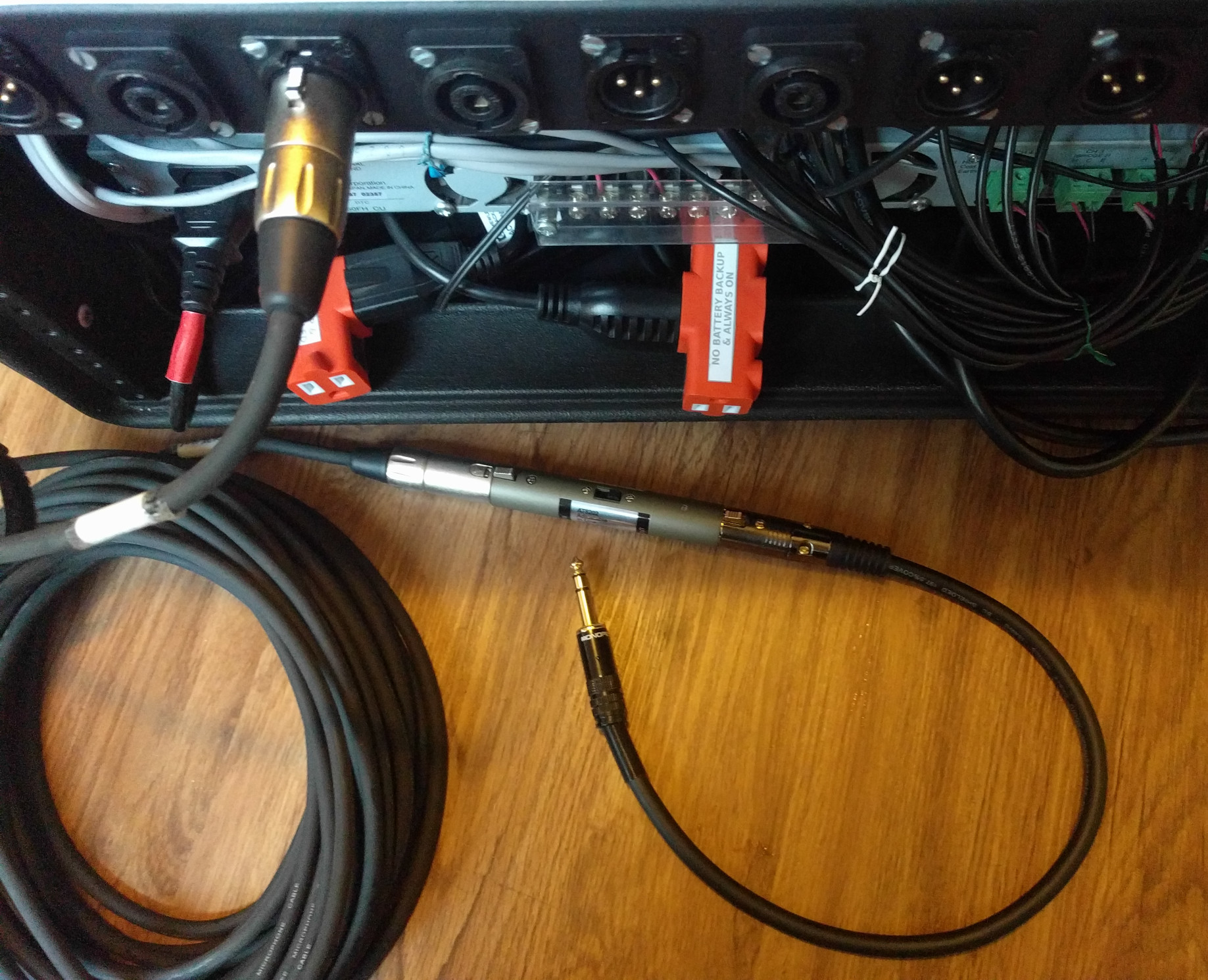
Output to secondary system, with microphone/TRS connection (omit attenuator for line level)

Output to assistive listening (headphones) transmitter
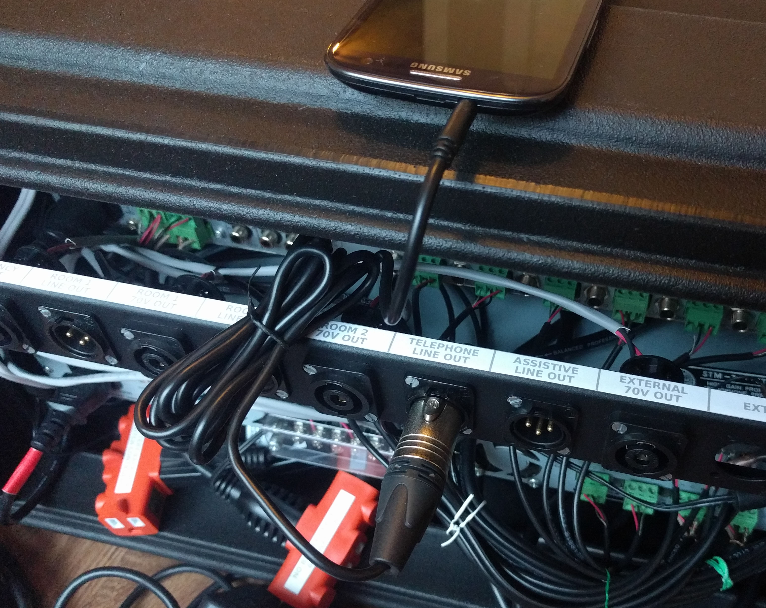
Output to cell phone for conference calling
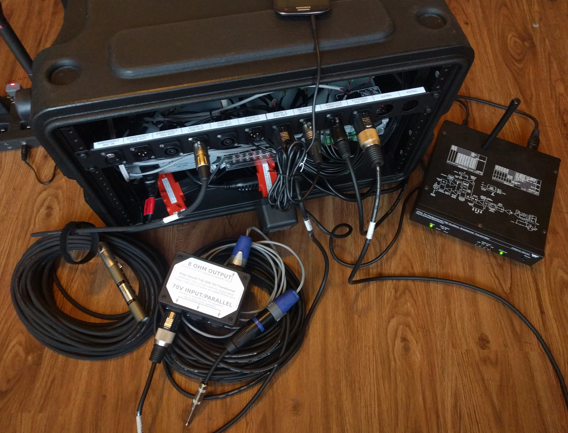
System with multiple connections: microphone/XLR output for room zone 1, one 8-ohm speaker for room zone 2, cell phone for conference call, assistive listening transmitter, and 70V for audio outside of the room

System with all its parts (excluding Williams Sound assistive listening receivers)

Emergency amplifier
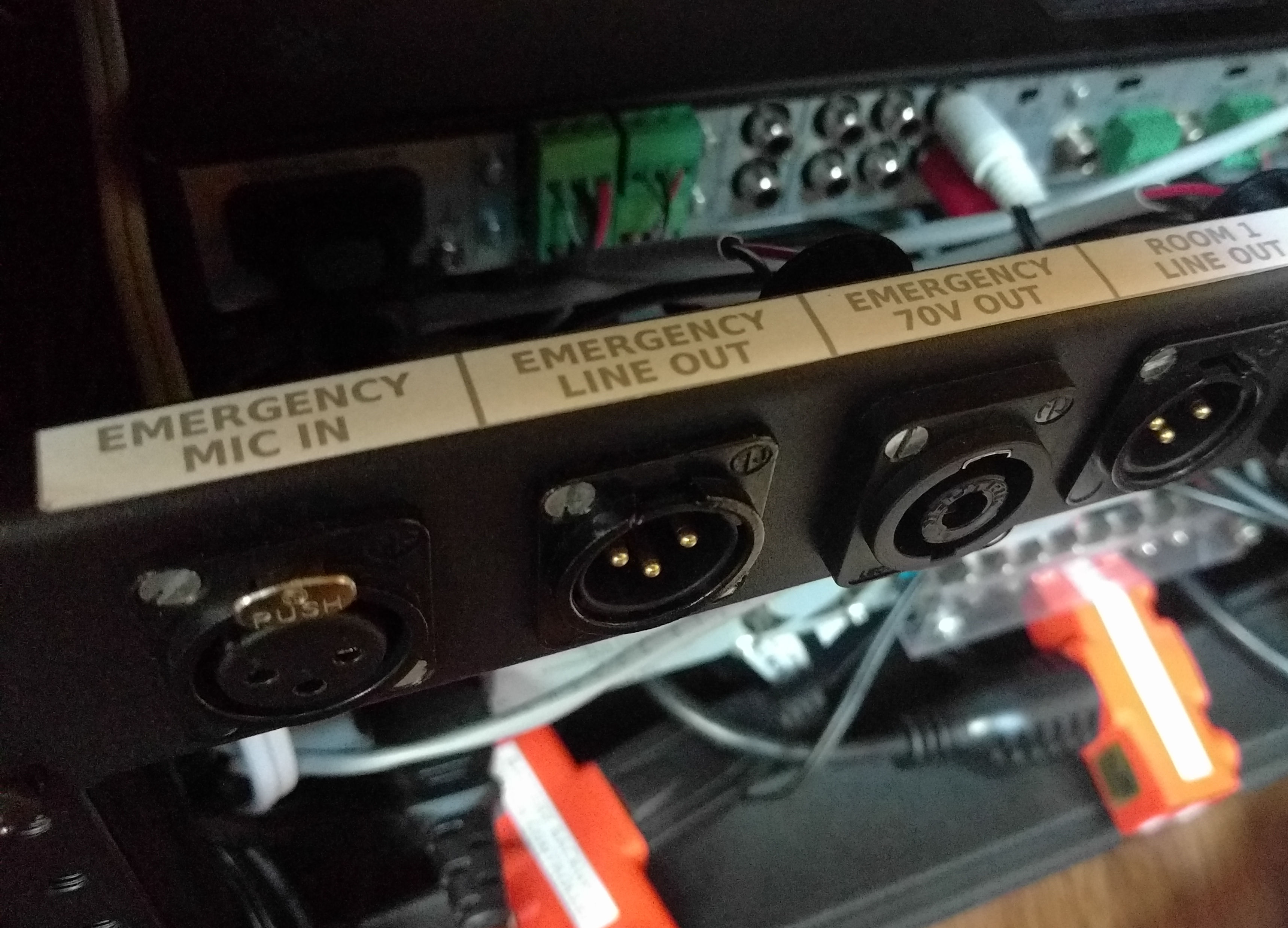
Emergency connections on rear panel

Extra power connections for transmitter and other accessories
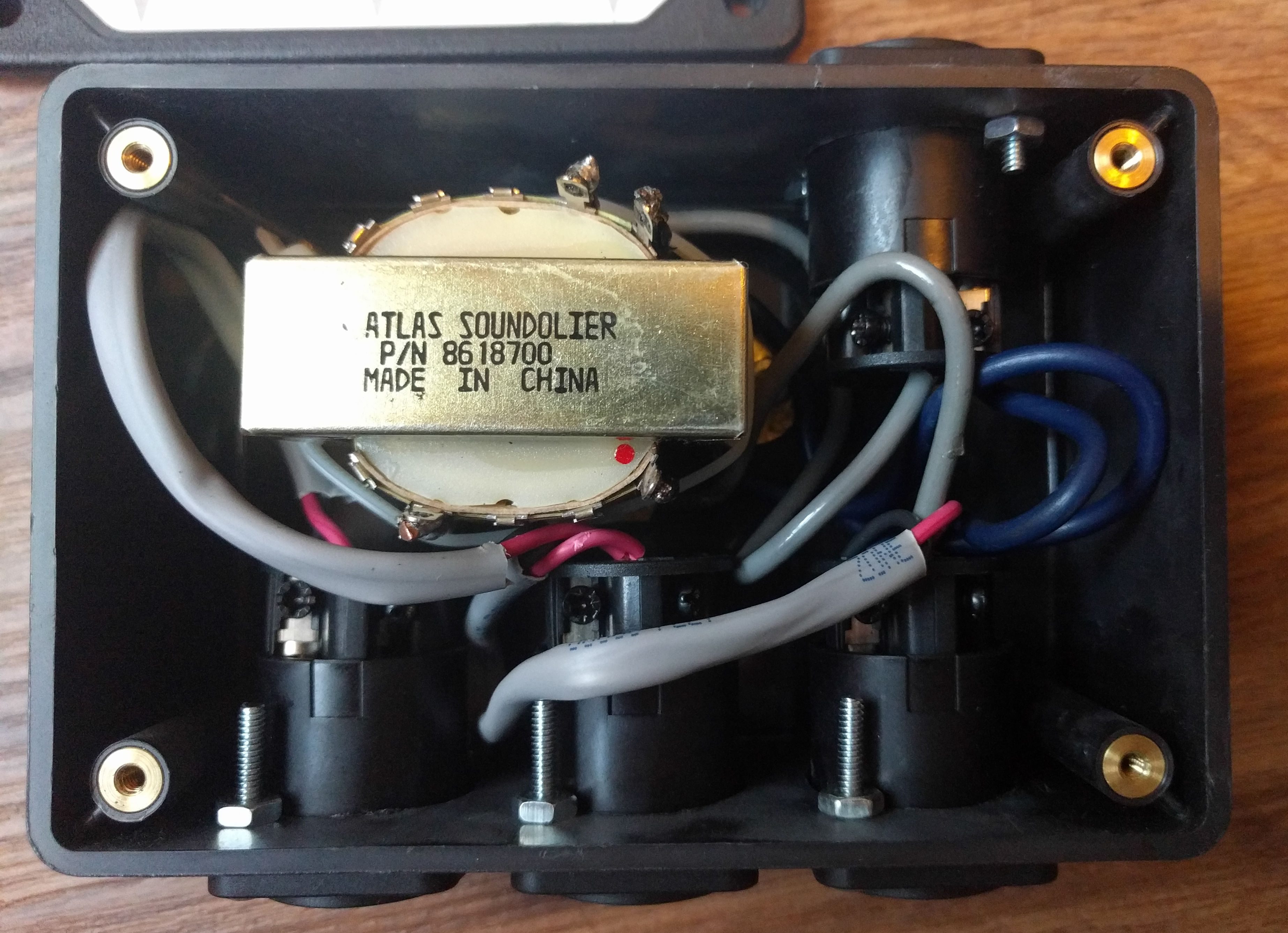
Inside the 70V transformer/splitter box
 Email
Email LinkedIn
 Twitter
 Reddit
 Facebook