Setup
Location: Find a place to operate the system. Take care to protect the rear panel connections from traffic. Connect the labeled power cable to the charger base and place all microphones in the base. Connect the primary AC power.
Room outputs: Connect to the room speakers using the ROOM1 LINE OUT or ROOM1 70V OUT connection. (It is possible to also use one of the ROOM2 outputs for a second speaker zone.) For more information and examples, see Room outputs, below. Carefully verify input/output levels and types: incorrect connections can damage equipment! Always make these connections with the main system powered off.
Power up: On the mixer, mute all seven inputs and set OUTPUT 1, OUTPUT 2, and EXTERNAL output levels to the north position. Power up the system with the button behind the door on the power supply. The lights on the Revolabs receiver will blink red/green while it starts up. Remove microphone 1 from the base and wait for it to connect (it will blink red). Press the button once to un-mute (it will blink green).
Check audio: Make sure all speakers are operational. Slowly increase INPUT 1 to the north position. Adjust amplifier levels, either at the amplifier (for 70V output) or a connected system (for LINE output). The mixer INPUT 1 and both OUTPUT knobs should be at the north position and the room sound should be at the high end of comfortable when speaking at a typical level.
Set up acoustic resonance control: Following the steps below for each room channel that is in use. Normally, this will only need to be done for the ROOM 1 output.
On the equalizer, make sure both channels are set to BYPASS.
On the mixer, mute input 1. Then use a paperclip to enable only output 1 in the input 1 section (only button 1 should be depressed). If you are setting up the ROOM 2 output, enable only the output 2 button.
Place microphone 1 on a stand in the center of the audience area. The microphone should be at a 45 degree angle pointing toward the front of the room.
On the mixer, again set input 1 to the north position. Make sure the room is quiet, then perform the ARC procedure by holding the ARC button with a paperclip for three seconds (until the ARC light begins to flash). Wait for the ARC procedure to complete.
If there is an error, the ARC light will flash rapidly and the procedure will abort; you will need to fix the problem and return to the previous step. If this happens before any measurement sounds are generated, check the input 1 assignment (step b. above). If there is an error following the first pair of measurement sounds, the input level is too low: increase the level at the amplifier (for 70V output) or the gain at the connected system (for LINE OUT connections). If there is an error following the second pair of measurement sounds, there is too much ambient noise: make sure the room is quiet. For more information, see page 18 of the manual.
When the ARC procedure is completed, the indicator of the ARC enabled output channel will flash orange for 1 second, then the ARC indicator will change to steady green.
Prepare the mixer for use: On the mixer, use a paperclip to depress all three output buttons on input 1. Input 2 should have only 1 and 2 depressed.
Set up assistive listening (if required): Connect the Williams Sound PPA T4 transmitter to ASSISTIVE LINE OUT. Always connect the antenna before the power!
The Audio Select should be set with switches 1,2,6,7 ON (down) and the rest OFF.
The FM Channel, Power should be set with switches 2-4 ON (down) and the rest OFF. Switches 1-5 will need be set differently if using a transmit frequency other than 72.9 MHz.
Set up the telephone interface (if required):
Use the kV Connection KM-IPHONE-MICX-A22 adapter cable to connect TELEPHONE LINE OUT and the cell phone.
Dial in to FreeConferenceCall.com with a paired cell phone. Use the dial string below. (The *5*5 switches to “presentation mode”, with all guests muted; the *8 disables the tones indicating when guests enter or exit the conference.)
<dial-in number> pp <access code> #pppp <host PIN> #ppp*5p*5p*8
Guests must be given the dial-in number and access code. For more information, see Telephone Output.
Operating
Using the microphones: When a microphone is removed from the charger base, it will automatically turn on. It will attempt to connect to the Revolabs base unit, and the light will flash green/yellow/red. When it has connected, the light will flash red, indicating that the microphone is MUTED. Press the button once to unmute the microphone, the light will flash green. When a microphone is returned to the base, it will turn off and switch to charging mode. To turn off a microphone for storage, hold the button until the light turns red and stays red, then release.
Inputs: There are six inputs connected to the mixer. Input 1 should always be used as the primary input, and input 2 should be used for lead singing (to avoid high audio levels to non-room outputs). A seventh input provides an isolated signal path for emergency use (see paragraph 4. below).
Custom equalization: The graphic equalizer can be used to tweak the sound on a particular room channel. Start with a flat curve before disabling the BYPASS. Note that the mixer ARC procedure applies its own room correction curve to each channel it is used on, this curve will remain active until the ARC system is disabled or set up again.
Bands below 100 Hz are not needed for speech.
To control proximity effect caused by speaking too close to the microphone, adjust the 100 to 400Hz bands.
To control sibilance, adjust the 2.5k to 10kHz bands.
Emergency: There are several failure modes anticipated by this design.
If AC power fails, the battery backup power supply will provide power for approximately 30 minutes. All devices will continue to be powered except for the charger base and the USB charger. The power supply will sound an on-battery alarm, this can be muted by holding the lower button for >3 seconds. A low battery alarm will still sound when the batteries are nearly empty. Press the lower button at any time to see various statistics about usage and run-time.
If a failure causes the entire wireless microphone system to be unusable, the EMERGENCY MIC IN can be used. Remove one of the microphone transmitters and connect the microphone directly with an XLR cable. Now use input 7 on the mixer.
If a failure causes the mixer to be unusable, the EMERGENCY MIC IN can again be used. Connect a microphone directly. Also connect the primary room output to either EMERGENCY LINE OUT or EMERGENCY 70V OUT. Control the level with channel 4 on the amplifier.
Room outputs
In most cases, only one of the four ROOM connections will be used: either ROOM1 LINE OUT or ROOM1 70V OUT. These two connections provide the same audio signal, but at completely different levels. Both are controlled by the ROOM 1 output on the mixer.
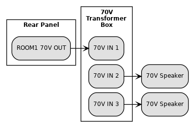
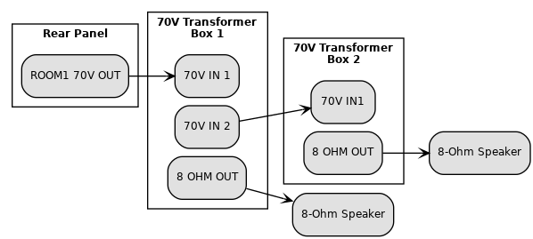
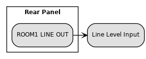
The following diagrams demonstrate the required connections for various scenarios.
For 70V speakers, use a direct connection from the 70V OUT to each speaker. The speakers can be daisy-chained by using the 70V transformer boxes as simple splitters: connect on the 70V side only. The speakers must have 70V transformers inside.
For 8-ohm speakers, use a 70V transformer box at each speaker. Connect the 70V OUT to the 70V INPUT of the first 70V transformer box. Connect the 8-OHM OUTPUT of the box to the speaker, using whatever adapters are required. For a second speaker, use the second 70V transformer box. This should only be used with plain, passive speakers with no 70V transformers inside.
For line level (-10 dBV, 0 dBV, 0 dBu, or +4 dBu), connect the LINE OUT to the input. This can be used with powered speakers or to connect to another sound system. This should not be used for a microphone level input. The UPS will not supply power to the external speakers or system in case of an outage.
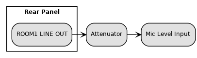
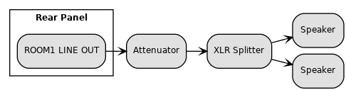
For microphone level (approximately -60 dBV), connect the LINE OUT through the AT8202 attenuator to the input. This can be used with powered speakers or to connect to another sound system. Set the attenuator to -40 dB. This can be adjusted in step 4 if the level is too low. The UPS will not supply power to the external speakers or system in case of an outage.
 Email
Email LinkedIn
 Twitter
 Reddit
 Facebook